AnyPortrait > Manual > Look At IK Controller
Look At IK Controller
1.7.0
There are two types of IK Controller used to move IK chains: "Position" and "Look At."
Among them, the Look At type IK Controller has been significantly improved in AnyPortrait v1.7.0.
Changes to its operation have led to the addition of various options.
This page covers the improved Look At IK Controller.
It explains the options corresponding to each stage of the procedural calculation process.
Special cases are also discussed.
We recommend reading the following manuals regarding IK Controllers first.
- IK Settings
- IK Controller
Applying Look At IK
Before diving into the details, let’s review how to set up a Look At IK Controller.
This explanation assumes that bones have been added to the mesh group and the IK chain has already been configured.
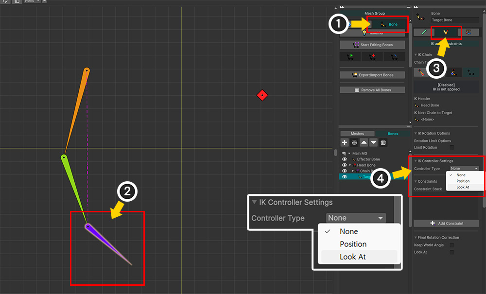
(1) Select the Bone tab.
(2) Select the bone to which you want to apply IK.
(3) Select the IK and Constraints tab in the right-hand UI.
(4) You can apply an IK Controller by changing the Controller Type option under "IK Controller Settings."
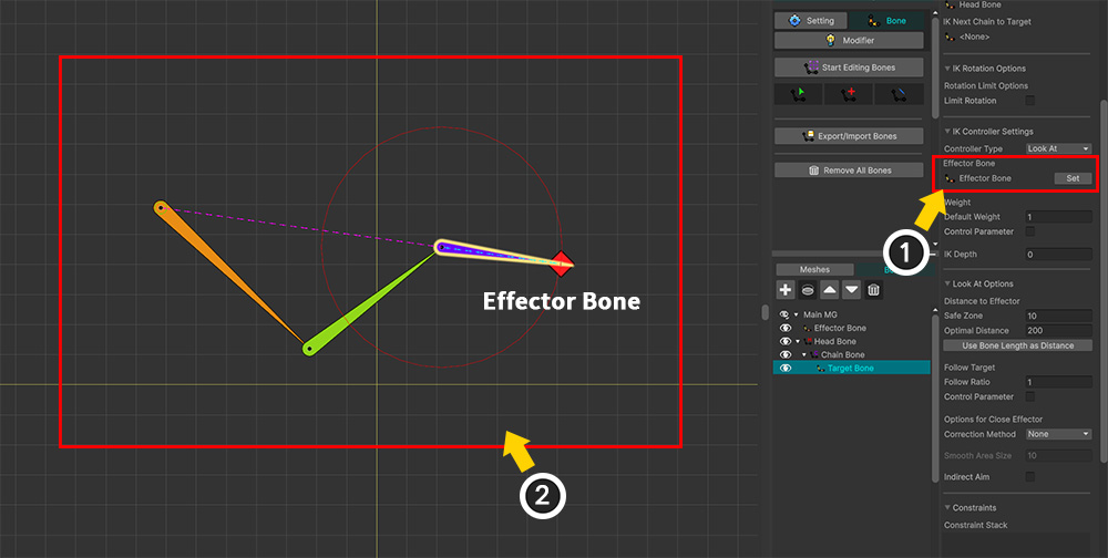
(1) Set the Effector Bone for the IK.
(2) You can see that the IK Controller is applied.
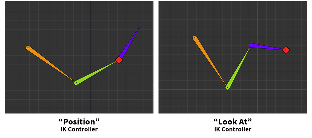
The way a bone follows the Effector Bone depends on the IK Controller type.
With the "Position" type, the bone moves so that its position aligns with the Effector Bone.
With the "Look At" type, the bone moves close to the Effector Bone and then rotates so that its tip faces the Effector Bone.
Look At Process
The improved "Look At" operates based on location and involves a three-step calculation process.
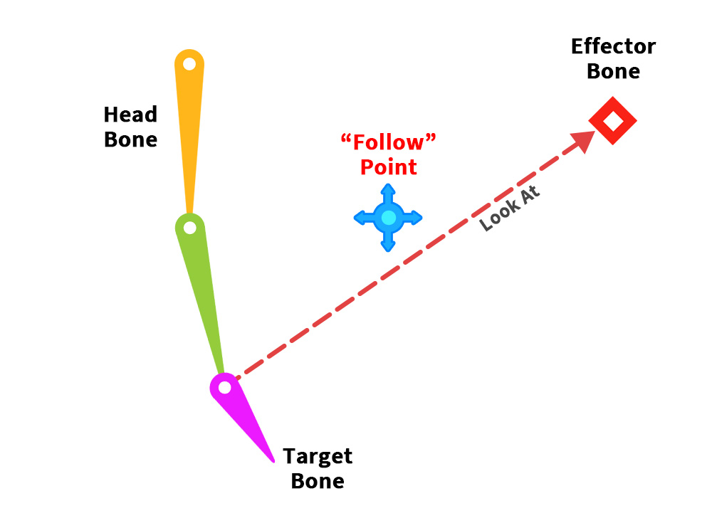
There is an IK chain connecting the Head Bone to the Target Bone.
The "Look At" IK is a setup where this IK chain causes the bone to "look at" the Effector Bone.
If we consider only the act of "looking," simply rotating the Target Bone would suffice.
However, allowing the Target Bone to shift slightly toward the Effector Bone would result in a more natural appearance.
Therefore, the goal of the first step is to determine the appropriate position for the Target Bone to move to—specifically, the "Follow Point."
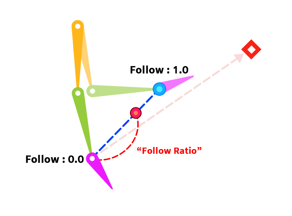
In Step 2, the final position to which the Target Bone is moved by the IK system is determined using the "Follow Point" calculated in Step 1.
The "Follow Point" represents the position the bone would occupy if it followed the Effector Bone as closely as possible.
The "Follow Ratio" option is used to determine the extent to which this "Follow Point" is applied.
In other words, if the "Follow Ratio" is 0, the Target Bone does not move from its original location but simply rotates in place.
As the "Follow Ratio" increases toward 1, the Target Bone moves progressively closer to the Effector Bone.
Additionally, the IK process is executed upon the completion of Step 2.
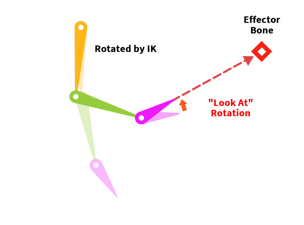
By the time Stage 2 is complete, the IK process has been executed, and the bones in the IK chain have moved.
Although the IK chain has moved toward the Effector Bone, the Target Bone is not yet perfectly aligned to face the Effector Bone.
Therefore, in Step 3, only the Target Bone rotates slightly further to face the Effector Bone.
Now, let's look at the options used at each step.
Step 1. Calculating the Follow Point
The goal of the first step is to determine the "Follow Point," the position toward which the Target Bone moves as naturally as possible.
The "Follow Point" uses the Effector Bone's position as its initial value and adjusts its location according to the following conditions.
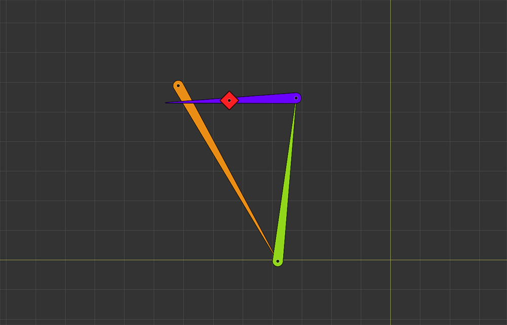
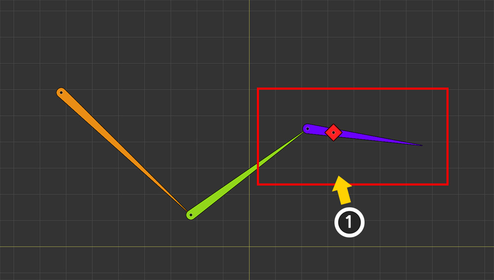
The first thing to consider is the case where the Effector Bone is too close to the head bone.
If the Effector Bone is close to the IK chain—specifically the Head Bone, which is the chain's starting point—it can easily result in an unnatural shape, as shown above.
Therefore, if they are too close, you need to disregard this proximity to some extent.
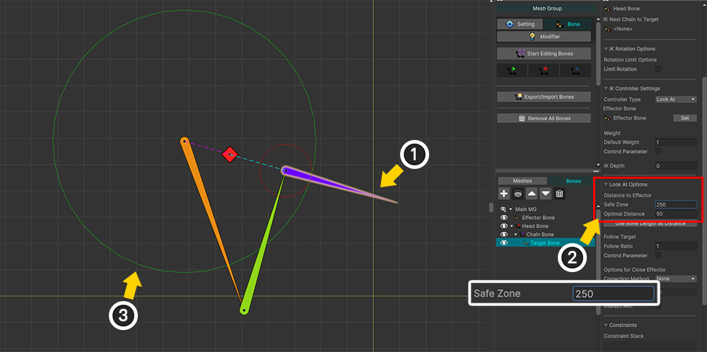
(1) Select the Target Bone to which the IK controller is applied.
(2) Increase the value of the Safe Zone option.
(3) You will see a green circle centered on the Head Bone expand based on the setting, and the Target Bone orienting itself outward from the Head Bone accordingly.
When the Effector Bone enters the Safe Zone, "Follow Point" is configured to treat the Effector Bone as if it were outside the Safe Zone.
This causes the Target Bone to face outward from the Safe Zone, as shown above.
The second factor to consider is the appropriate distance between the Target Bone and the Effector Bone.
The primary difference between "Look At" and "Position" type IK controllers is whether the Target Bone moves to align its position with the Effector Bone.
With the "Look At" IK controller, the Target Bone and the Effector Bone must be separated by an appropriate distance.
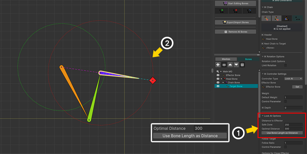
(1) Change the value of the Optimal Distance option. (Clicking the Use Bone Length as Distance button automatically enters a value based on the bone's shape.)
(2) A red circle is drawn around the Target Bone based on the entered value, and you can see the Target Bone and Effector Bone positioned apart by that distance.
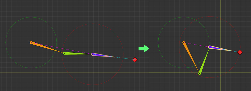
The third point to consider is how the IK chain behaves as the Effector Bone approaches.
While the first case concerned the "minimum range," what we are discussing here is the overall shape of the IK chain.
As shown in the image above, the Effector Bone has not yet entered the "minimum range" (indicated by the green circle), yet the shape of the IK chain has already changed significantly.
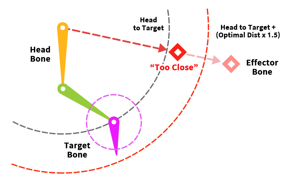
In the "Look At" IK ㅊontroller, the system recognizes that the "Effector Bone has come close enough" if the distance between the Effector Bone and the Head Bone is less than the following value:
"(Distance between Head Bone and Target Bone) + (Optimal Distance value x 1.5)"
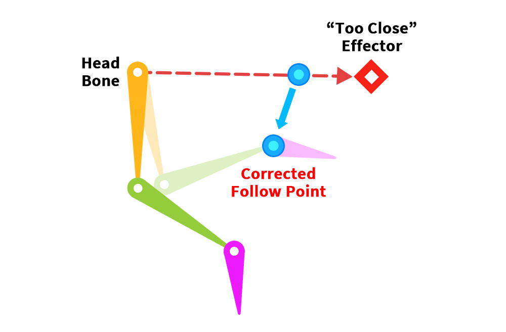
When the Effector Bone comes within range, the "Follow Point" is shifted slightly to ensure the IK-driven pose looks natural.
The closer the Effector Bone gets, the stronger the positional correction becomes.
The following options are used to determine how the "Follow Point" moves.
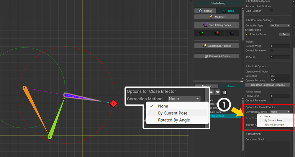
The method for adjusting the position of the "Follow Point" is determined by the Correction Method option under "Options for Close Effector."
- None: Do not move the "Follow Point."
- By Current Pose: Move the "Follow Point" based on the pose held immediately before the "Look At" IK Controller activates.
- Rotated By Angle: Set the "Follow Point" at a position rotated by the specified angle relative to the head bone.
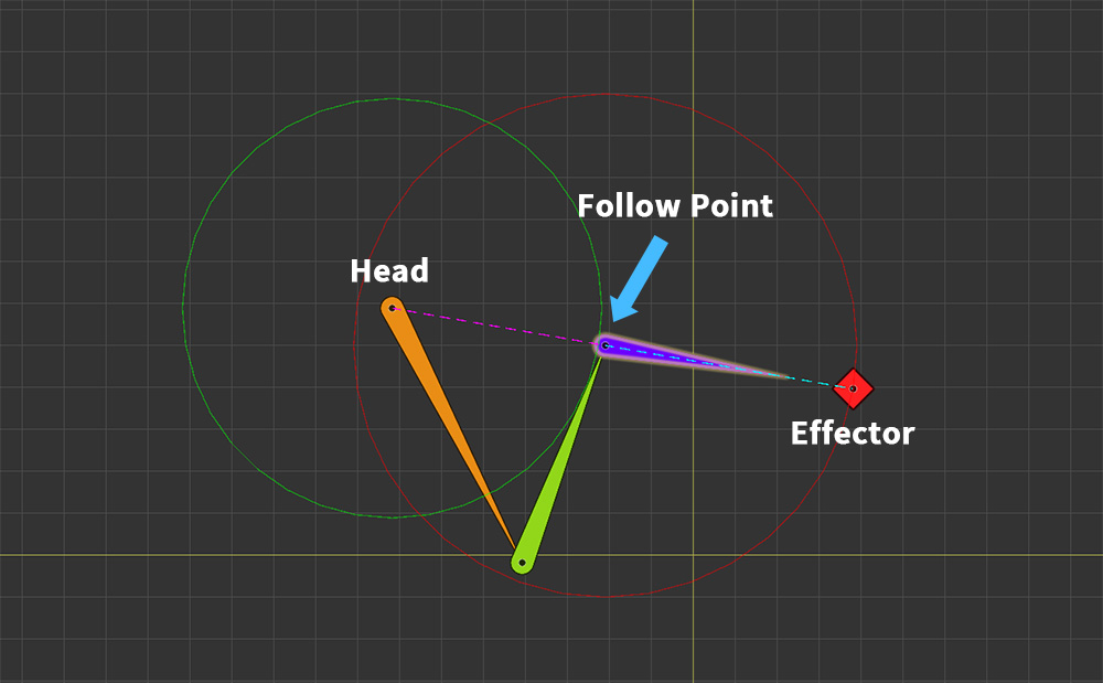
You can achieve the result shown above by setting Correction Method to "None".
By default, the "Follow Point" is positioned on the line connecting the Head Bone and the Effector Bone.
Unless the Effector Bone is positioned too close, the "None" method does not move the "Follow Point", resulting in the behavior shown above.
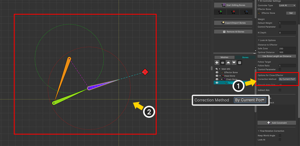
When Correction Method is set to "By Current Pose", the "Follow Point" shifts, altering the IK result as shown above.
This method operates based on the pose immediately preceding the activation of the Look At IK Controller (accounting for FK, previously active IK Controllers, and so on).
Since the "Follow Point" moves toward the IK chain's Target Bone, the resulting movement appears more natural.
Let’s observe how this method works in the animation editing view.
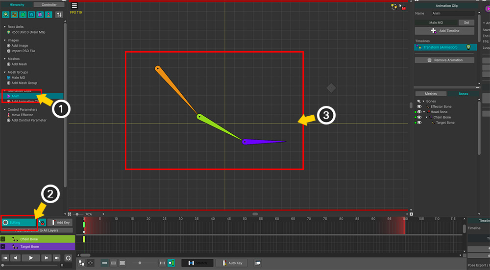
Create an Animation Clip, enable Animation Edit Mode, and then move the IK chain bones appropriately to complete the FK pose.
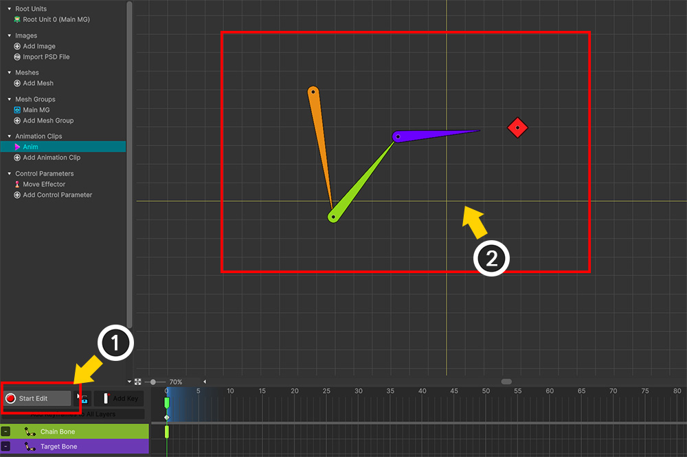
Turning off Animation Edit Mode activates the IK controller.
If you observe the result of the "Look At" IK Controller at this stage, you will see that the IK chain's Target Bone is positioned slightly lower while facing the Effector Bone.
This is because the Target Bone was positioned lower in the pose originally created using FK.
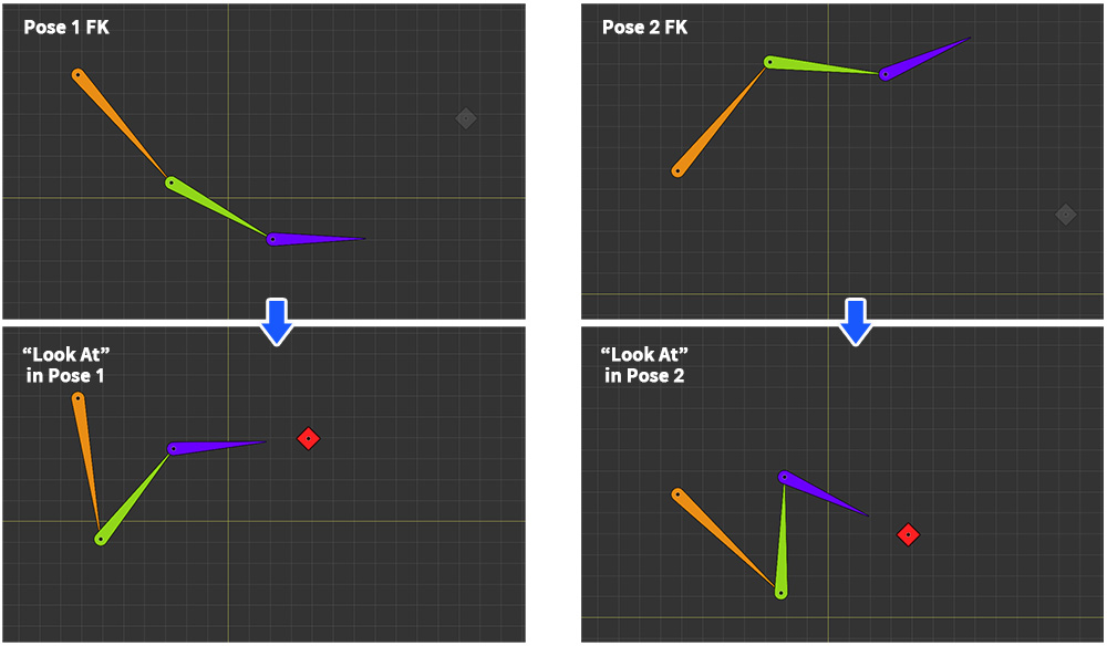
Therefore, setting the FK pose differently results in a different outcome for the "Look At" IK controller.
As shown in the image above, the result of the "Look At" IK Controller changes depending on the two poses.
In particular, please note the position of the Target Bone relative to the line connecting the Head Bone and the Effector Bone—specifically, whether it is located above or below that line.
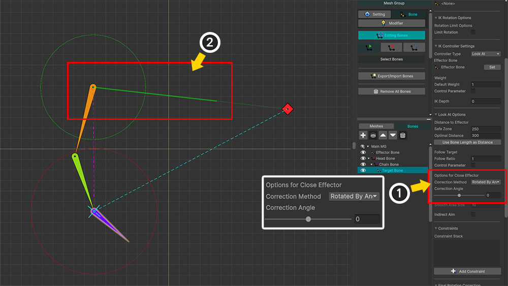
When Correction Method is set to "Rotation By Angle", a green guide line extending from the Head Bone appears.
This green line indicates the direction in which the position of "Follow Point" is being corrected.
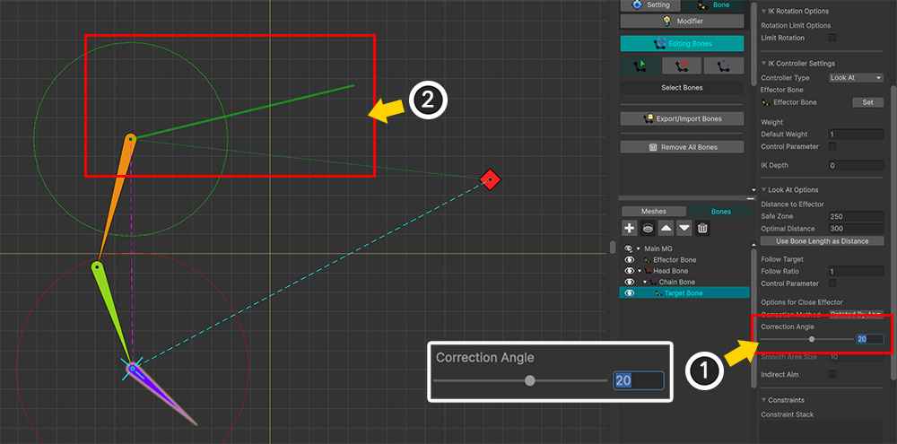
When you change the Correction Angle value, you can see the green guide line rotating around the Head Bone.
The "Follow Point" is located on the vector connecting the Head Bone and the Effector Bone; "Rotation By Angle" rotates this vector to adjust the position of the "Follow Point".
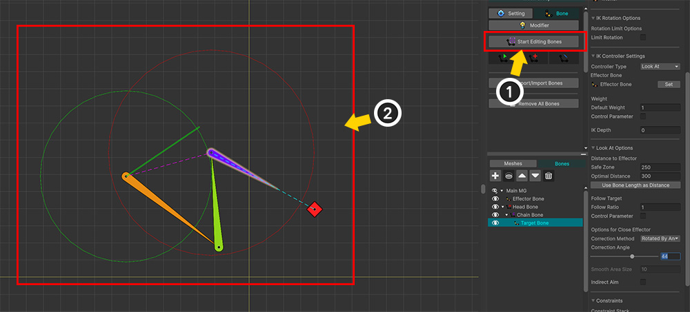
If you turn off Edit Mode in this state, the "Look At" IK Controller activates, allowing you to see the result.
The Target Bone moves according to the Correction Angle value, which indicates that the "Follow Point" has shifted by that amount.
Note
The option values applied when moving the "Follow Point" represent the values at the point of maximum possible movement.
As the Effector Bone moves further away, the degree of positional adjustment gradually decreases, resulting in less actual movement than the value entered.
Step 2. Executing IK with the Follow Ratio
The "Follow Point" obtained in Step 1 represents the position the Target Bone would occupy if it followed the Effector Bone as closely as possible.
If the "Follow Point" is applied fully, the bones in the IK chain tend to move significantly.
If only a small amount of the "Follow Point" is applied, the IK chain bones move minimally, while the Target Bone rotates toward the Effector Bone.
The result of the "Look At" IK Controller varies significantly depending on the extent to which the "Follow Point" is applied.
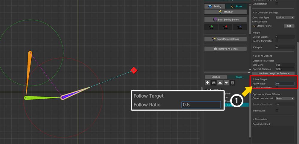
(1) You can determine the extent to which the "Follow Point" is applied by using the Follow Ratio option under "Follow Target."
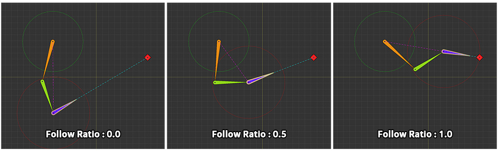
The Follow Ratio ranges from 0 to 1, and adjusting this value alters the IK result as shown above.
When Follow Ratio is 0, only the Target Bone rotates, yielding the same result as the "Single Bone Look At" described below.
As Follow Ratio approaches 1, the Target Bone moves toward the Effector Bone.
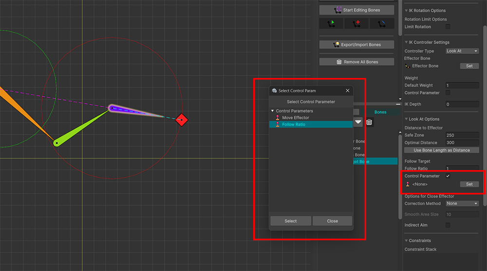
The value of Follow Ratio can be controlled using a Control Parameter.
By enabling the Control Parameter option and selecting a "Float" type control parameter, you can change the Follow Ratio in real time.
Step 3. Rotating the Target Bone
IK is executed once Step 2 is complete.
While IK moves the bones in the IK chain, the Target Bone is not yet oriented toward the effector bone even after the IK process finishes.
Therefore, Step 3 involves rotating the Target Bone to face the Effector Bone.
At this Step, the Limit Rotation option for the IK chain can be used to restrict the Target Bone's rotation.
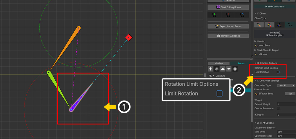
(1) Select the Target Bone.
(2) Enable Limit Rotation among the IK chain options.
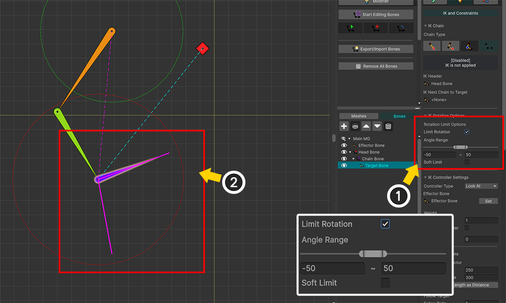
(1) Adjust the Angle Range value.
(2) You can see that the rotation angle of the Target Bone is restricted by the option.
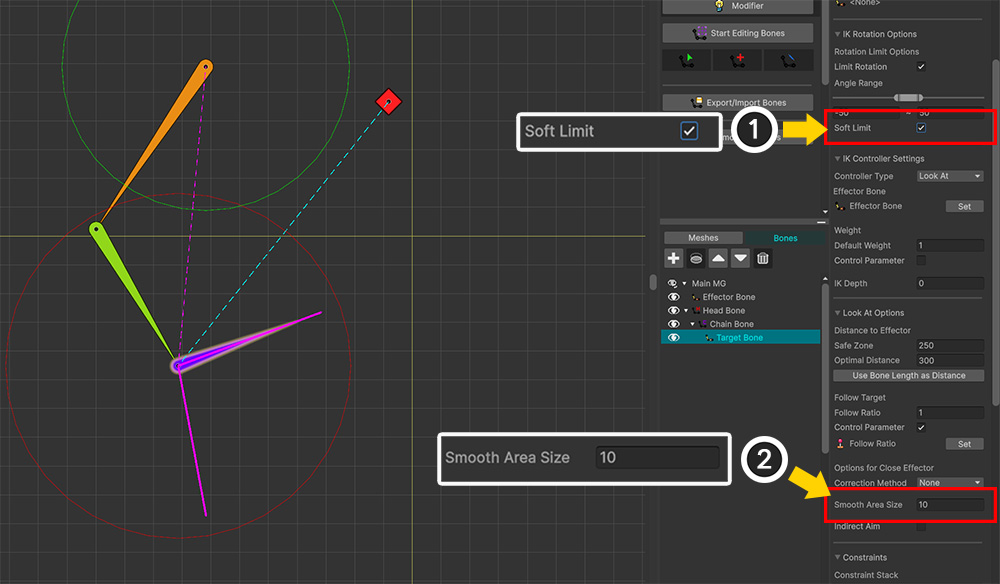
If you wish to apply a smooth limit to the rotation angle, you can use the options above.
(1) Enable the Soft Limit option.
(2) Smooth Area Size defines the angular range over which the limit is applied smoothly. Increasing this value results in a gradual limitation across a wider angular range.
The Soft Limit for the Target Bone operates as follows:
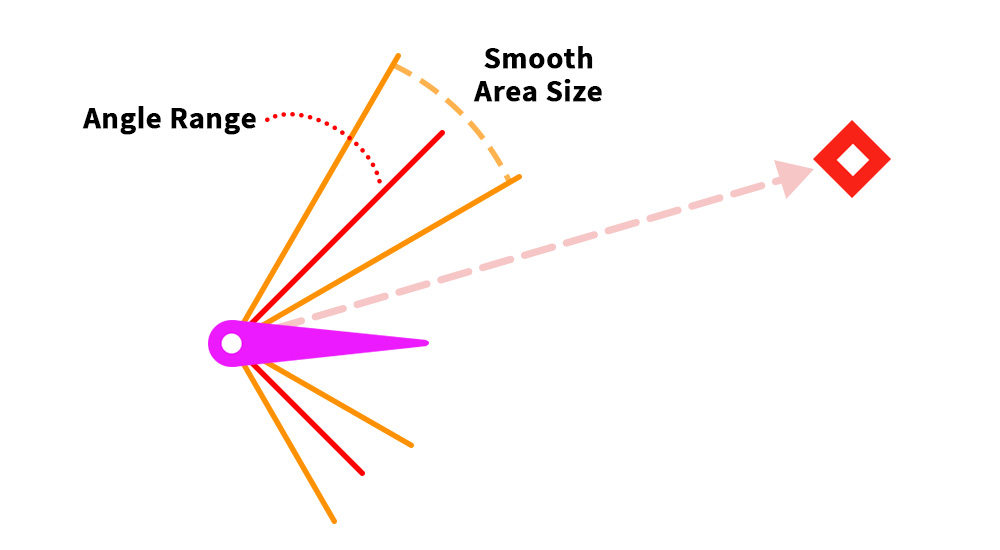
The angle limit of the Angle Range is relaxed by the angle specified in the Smooth Area Size option.
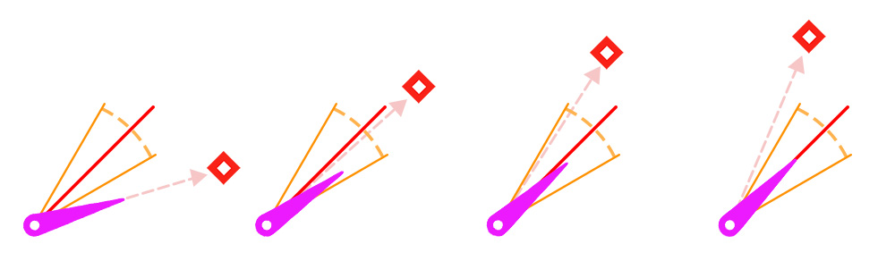
When the angle toward the Effector Bone falls within the Smooth Area, the Target Bone gradually "looks less" at the Effector Bone.
If the angle toward the Effector Bone lies outside the Smooth Area, the Target Bone rotates by the angle specified in the Angle Range and then stops.
Once step 3 is completed, the operation of the "Look At" IK Controller is finished.
"Look At" of a Single Bone
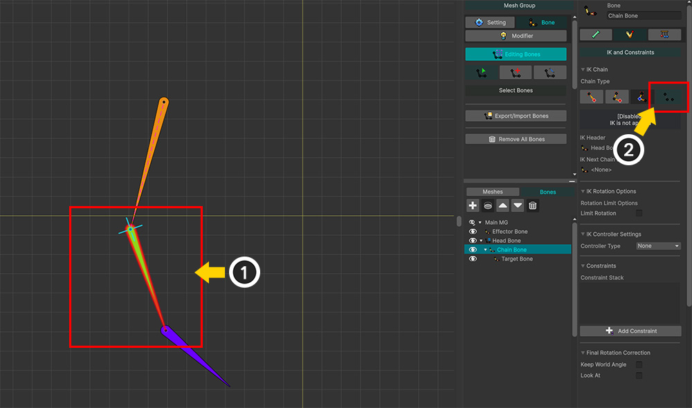
If you apply a "Look At" IK Controller to a bone that is not part of an IK chain, the system skips the IK calculation and performs only a simple rotation.
(1) Select the parent bone.
(2) Release the IK chain leading to the child bone, or set up the IK chain to target a different bone instead.
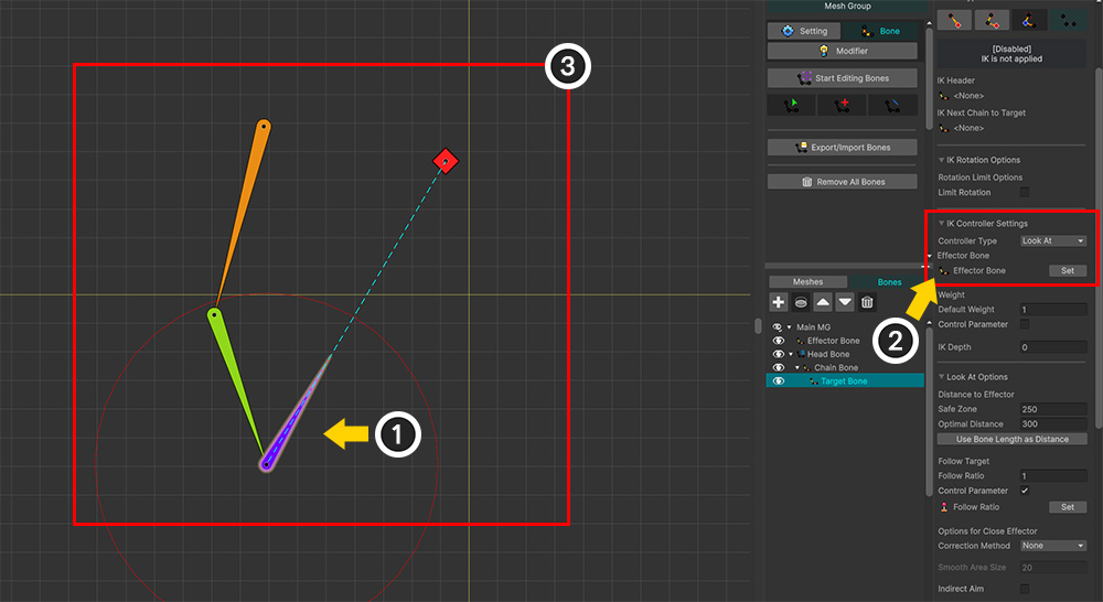
(1) Select the bone to which the IK will be applied.
(2) Set up the "Look At" IK Controller.
(3) Since there is no IK chain, you can see the bone rotating independently to face the Effector Bone.
Indirect Aim
The role of the "Look At" IK Controller is to make the Target Bone face the Effector Bone within an IK chain.
However, there are certainly cases where you need a bone other than the Target Bone to face the Effector Bone.
A prime example is "a hand holding a gun".
The muzzle needs to point at the aiming target, but since the IK is applied to the hand, the result would be inaccurate.
Even if you applied the IK chain to the gun itself, the IK might not function correctly because the gun and the hand are fixed relative to each other.
The option used in this scenario is Indirect Aim.
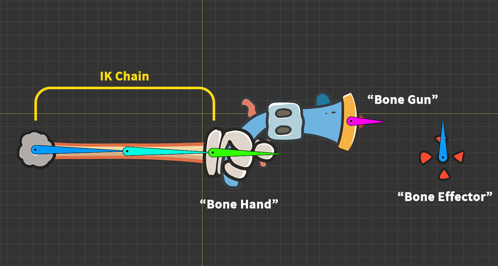
We have prepared a simple example as shown above.
The bone representing the muzzle, "Bone Gun," is currently connected as a child of the IK chain's bone, "Bone Hand."
Next, we will create "Bone Effector"—representing the aiming point—and set it as the target for the "Look At" function.
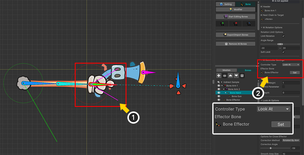
(1) Select "Bone Hand".
(2) Set up a "Look At" IK Controller targeting "Bone Effector".
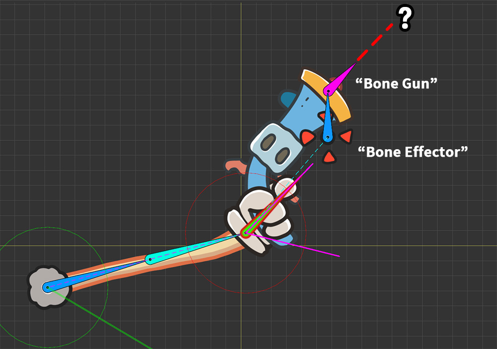
At first glance, moving the "Bone Effector" seems to work well.
However, a closer look reveals that the IK controller operates independently of the "Bone Gun," meaning the gun fails to aim correctly.
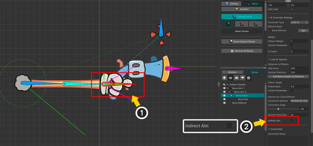
(1) Reselect the "Bone Hand" to which the "Look At" IK controller is applied.
(2) Enable the Indirect Aim option.
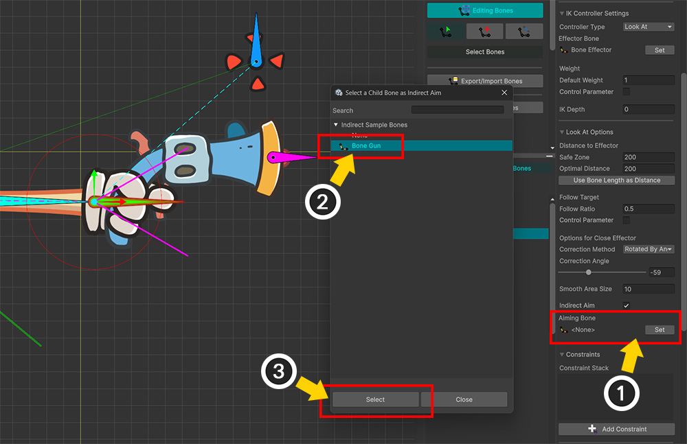
(1) Press the Set button.
(2) The child bones of "Bone Hand" appear, and select "Bone Gun" here.
(3) Press the Select button.
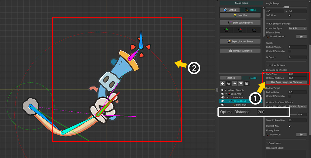
You need to readjust the optimal distance from the "Bone Effector" based on the "Bone Gun."
(1) Increase the Optimal Distance value so that (2) the "Bone Gun" falls within the red circle.
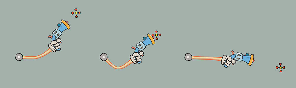
If you check the results, you can see that the gun, not the hand, is properly aimed.